Rowandale Canal Basin - Development History of Section Two


As before the base is made from
two 50mm slabs of builders
insulation board, glued together
with Evostik Impact Adhesive.
The top surface is the zero base
level for the track, and will align
vertically with the goods yard area
of the first section. This provides a
light and rigid base; the same
technique was used for the first
section.
Other layers of board are glued to
this to give elevated track and
background hills, and river valleys
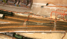
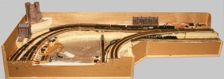
will be cut into it. The top photo
shows the initial rough cut with a
print out of the track.
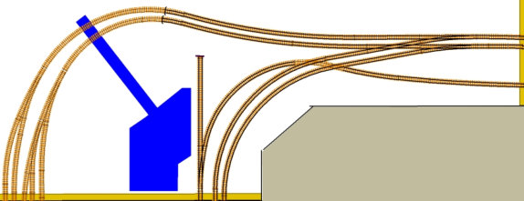
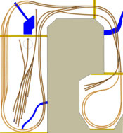
This is the track plan for the five foot corner section which attaches to the
open end of the first town & station section. This will contain an extension
of the town, together with a section of canal, with lock & canal basin.
Then moving into open moorland with the track rising on a 2% to 3%
gradient. At the left are the ends of the hidden storage loops which become
the double main line, which rises to join the other part of the main line
coming from the raised station. The single track access to the goods yard
passes under this and will rise to join the main line in the next section.
This section was started in November 2018.
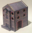
The mill building and a castle or folly have been build from card
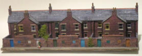
kits, ready to place on it. A low relief terrace of houses, from the
rear of Archie’s Yard, will also be moved to this section.



The plywood side panels have been
glued to the foam base with a building
adhesive ( Everbuild StixAll) This has
high-grab and excellent gap-filling, so
where the vertical edges of the foam
base are inevitably far from exact, the
glue forms a good joint. Corners are
reinforced with right angle mouldings.
Rather than use thin MDF as the base
for the track, a double layer of 3mm
grey-board has been used; glued
together with a PVA based
woodworking adhesive. The grey-board
was cut from A3 sheets with the joints
staggered ( as in brick laying ). This was
much easier to cut to shape than MDF
and results in a strong but slightly
flexible base; ideal for gradients. The
grey-board was then glued to the foam
base with the building adhesive.
The usual cork strips were then glued along the track line with
a generous layer of Copydex adhesive, and the track glued on
top of this with just a thin layer of Copydex, weighted down
with large paint cans or books till dry. Laid like this the track
can easily be lifted, if required, by sliding the full blade of a
snap-off blade craft knife underneath it.


Further work on this section will be postponed until the base layers and track is laid for the
remaining sections. The alignment dowels and clamping magnets have not been fitted yet.
So that trains can be run again as soon as possible, these sections will
initially just have the track bases, track laid and ballasted, together with basic
topography. Points control and isolation sections will then be connected to the
computer for route selection from the control panel. Buildings and scenery
will then be added to each section in turn.

The development of the sections of Rowandale; are each recorded on separate pages.

Not much modelling work has been done over the summer. However the layout has now moved upstairs to
a spare bedroom and the shape of the planned extension layout has been changed from a long ‘L’ to a more
compact ‘U’ shape. The supporting frame has been built and all three of the new sections have been
constructed. The track has been laid to all the new sections and the tracks aligned across the baseboard
joints.
This corner section will now feature
a canal lock with lock-keeper’s
cottage and canal basin.
The lock, cottage and one narrow
boat have been constructed; again
from Scalescenes card kits, and can
be seen in detail here on the
Buildings Page.
The basic topography on Section Three will be brought to this same level
before further work done to finish this section.
Baseboard sections are aligned with two engineering dowel pins & sockets, and
held together with two 25mm diameter magnets (22kg force) acting on 30mm
diameter steel washers.
These are all set into a pair of abutting 50x25 mm wood beams (shown in
orange on the track plan) which are glued into the foam base, aligned with
the top edge. Tests showed that using Everbuild StixAll building adhesive
resulted in a strong joint with the insulation board, adhering well to both
surfaces, and with excellent gap filling qualities; better than other
adhesives I tried.

Where the tracks cross board joints, they have been soldered to a 20mm wide strip of PCB, with
appropriate cuts in the copper surface to provide the track insulation. The cork underlay was removed
under the PCB and packing strips of grey-board are inserted under the copper strips, to match the
thickness of the cork. The PCB strips are then fixed with screws either side of each track, reaching down
into the wooden end beams. During soldering the tracks were aligned by eye. The vertical alignment of the
adjoining track ends can then be tweaked by adjusting the screws; compressing the grey-board.

The method of joining adjacent boards,
described above, has proved very satisfactory;
the magnetic clamps hold the baseboards firmly
and accurately together without the need for
any other clamping devices. To separate
adjacent baseboards a couple of large screw
drivers are needed to lever them apart!
The strength of the glued joint between the inset
wooden end beams and the insulation board has also
proved to be very robust, with no sign of separation.
The plywood side panels have also stayed firmly
attached to the sides of the insulation board, despite
some rough handling when forgetting they were only
glued!
The end result has been four very solid and fairly light
baseboards, easily carried by one person.


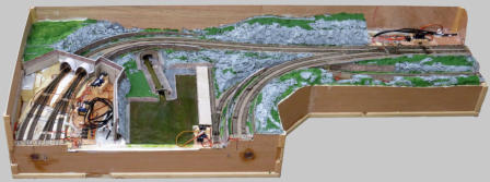
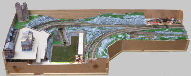
The basic topography of this corner section
completed with the canal lock and basin in
place. The hills have been built up with
scraps of the builders foam, overlaid with
low density filler and roughly painted for
areas of bare rock & moorland.
The area at bottom left will have a removable
raised part of the town, covering the point servos
for the hidden storage lines. At top right, these
servos and controller will be covered by a lift-off
section of moor and a signal box .
A tentative positioning of buildings is shown at left.
The full plan is shown here:
Update
Menu
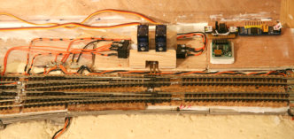
The DCC bus-wires are now in place and
wired to the tracks. The points servo
motors have been fitted, together with
micro-switches for the frog polarity and
switching of isolation sections. Note that
one of the servo motors has had the
thickness of the operating arm increased
( two extra part arms glued to it ) so as
to operate a second
micro-switch for the
two track isolation
sections of the
double track cross-
over.
