Rowandale - Station & Town - Section One
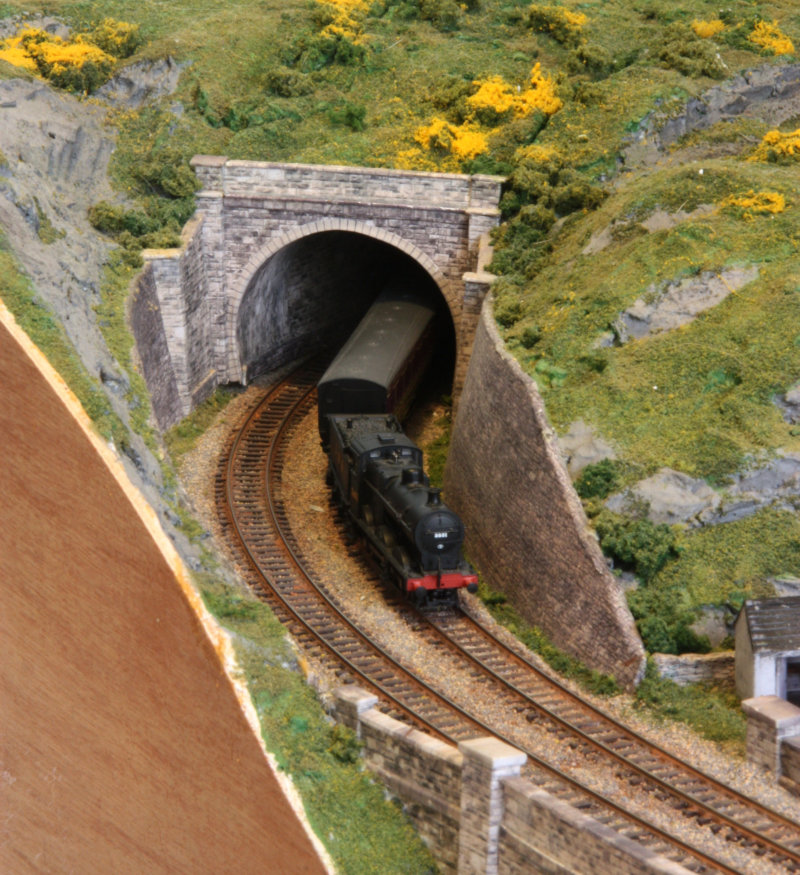
Rowandale is loosely based on the Settle Carlisle
line in North Yorkshire, in the late LMS period;
mostly steam - with only a diesel shunter. The first
section is shown in the track plan below; the fainter
lines are hidden track.
Work is concentrating on this first section.
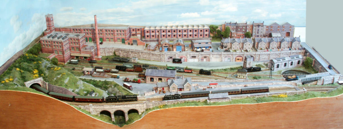
The hidden storage sidings at the rear are under the
town, central is the quite extensive goods yard, with
the station in front of it on the gently rising main
line. At the bottom left the main line crosses a
viaduct, over the river, before entering a tunnel.
The base is 5ft by 2ft 6” and is formed from two layers of
2” building insulation foam, into which is carved a deep
river valley under the viaduct. Extra height has been added
over the tunnel at left with expanding foam. The track bed
is formed from thin MDF board with cork on top. Edges are
protected with 1/8” ply glued to the foam board; this has
proved strong, stable and very light; surviving the removal
van with no damage.
The track is Peco Code-55 with Electro-frog points.
Small button magnets are buries at various locations in the
sidings to operate the DG Couplings on the rolling stock.
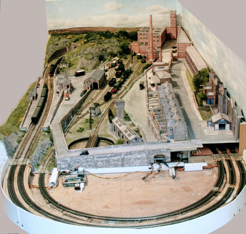
Temporary semicircular tracks, on a ‘D’ shaped board,
have been added at the right hand end to allow
continuous running on the main line and give access
to the goods yard.
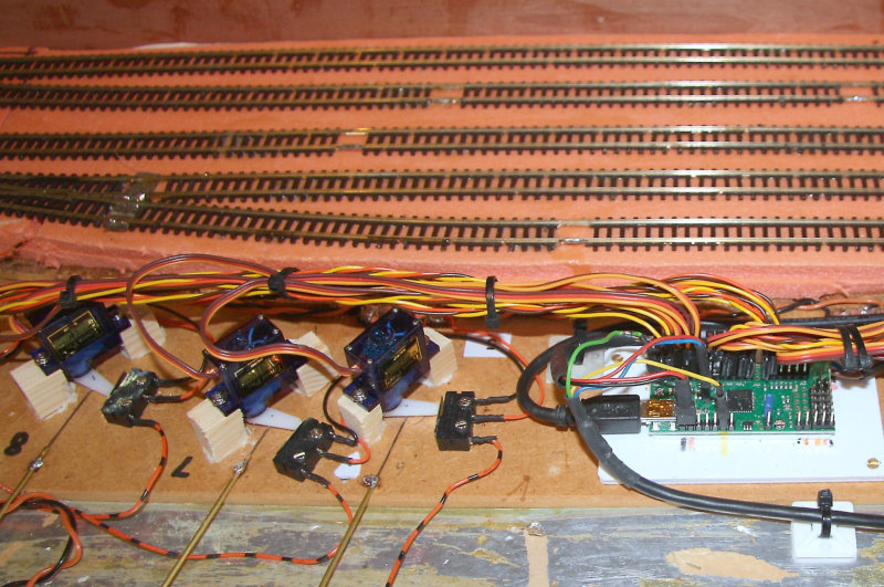
Miniature model aircraft servo motors (Type SG-90)
are used to operate the points; the servos being
mounted just in front of the rear storage tracks and
are connected to the points by the wire-in-tube
method.
The servos are controlled by a small dedicated
module, a Pololu Maestro Servo Controller. This is a
micro-processor system which has been programmed
to accept a route number, sent by a Raspberry-Pi
micro computer in the control panel, so that various
routes in the sidings and main line can be set with
just a single push-button on the control panel. The
polarity of the frogs on the points are set with micro-
switches operated by the servo motor arms.
Control of the locos is using the free open-source
software JMRI DeCoder-Pro, running on a second
Raspberry-Pi micro computer, with the interface to the
track via a USB connection to a SPROG 3, which in
turn generates the DCC signals for the track.

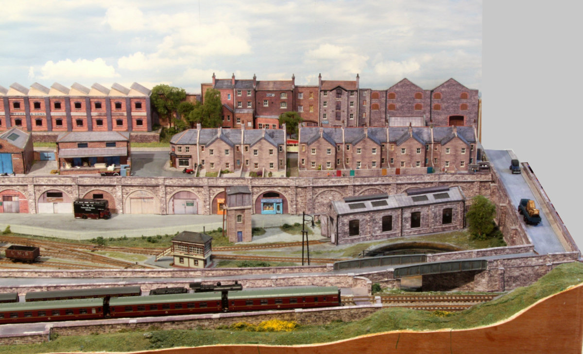
Track Plan of goods yard & station section - with temporary ‘D’ loops
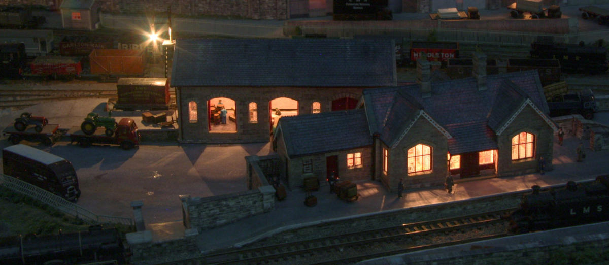
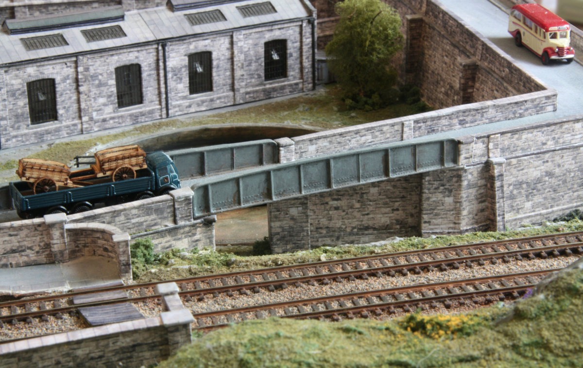
This shows the station approach road and bridge over
the entrance track to the goods yard. together with
the station yard, small goods store and groundwork in
the goods yard, including fencing.
The engine shed, water tower and turntable are also
shown.
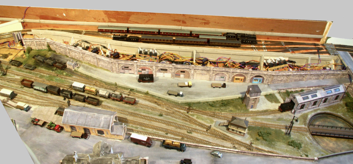
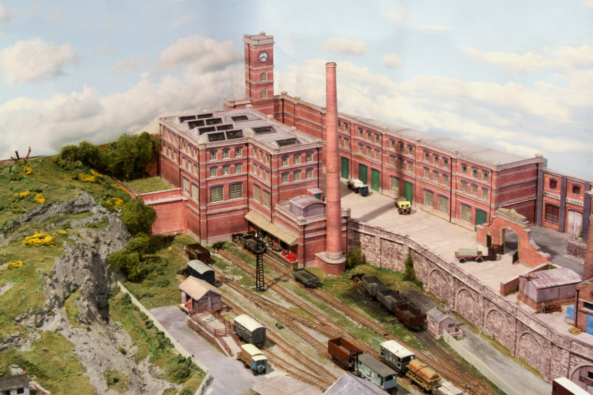
Retaining walls, with storage units and a couple of
shops under the arches, are at the rear of the goods
yard, with road access via a ramp. A coal merchants
office is also here.
Above the retaining wall, at the level of the main
town, are various buildings. The front half of this
raised section covers the servo motors and controller,
which operate the points. The rear half covers the
hidden holding tracks.
The buildings over both of these areas are mounted as
removable modules to allow access to the tracks & servos
underneath.
Some of the buildings were originally on the rear of Archie’s
Yard, which was originally intended to be a quick lash-up,
but did become a full layout.
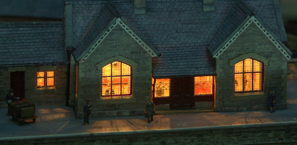
The Midland Railway built its stations to a common design,
with three size variations to suit the importance of the
station. The station in the layout is based on the small
design. They all had characteristic windows and distinctive
filigree design of the barge-boards at the roof edges. The
goods shed also had distinctive windows. One small
business AMBIS Engineering has produced an excellent
brass fret of these details for the station & shelter, the
goods shed and station master’s house.

A Raspberry-Pi 3B computer is mounted inside the
control panel and is used to control the routes for
the layout and the displays.
A full description of the control system, points
controller and loco position sensors is given here:
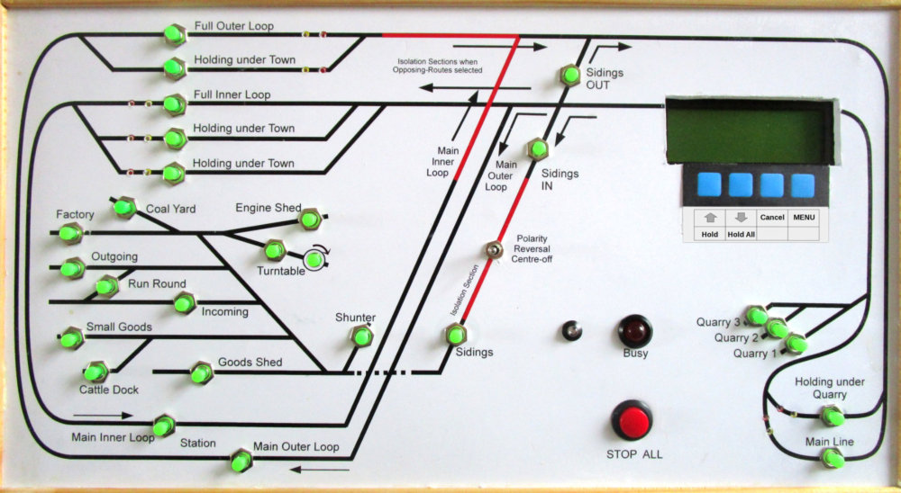


Rowandale has a comprehensive control & mimic panel.
It is A3 size and fitted with route selection push buttons,
together with tiny LEDs which indicate the position of locos
in the hidden holding bays.
To set a route, pressing just the one push-button which lies
on the desired route, will set all the points that are required
to establish that complete route.
There is also a four line by 20 character display screen which
indicates the previous routes that have been set.
The associated keypad, can be used to perform a number of
functions, such as setting the default routes, initiating train
lap timing functions, and train holding features.
It is also used to perform various system tests, such as
checking all the LEDs on the control panel.


Click on
, for a blog of the Development of Rowandale.
For detailed photos of the buildings see:


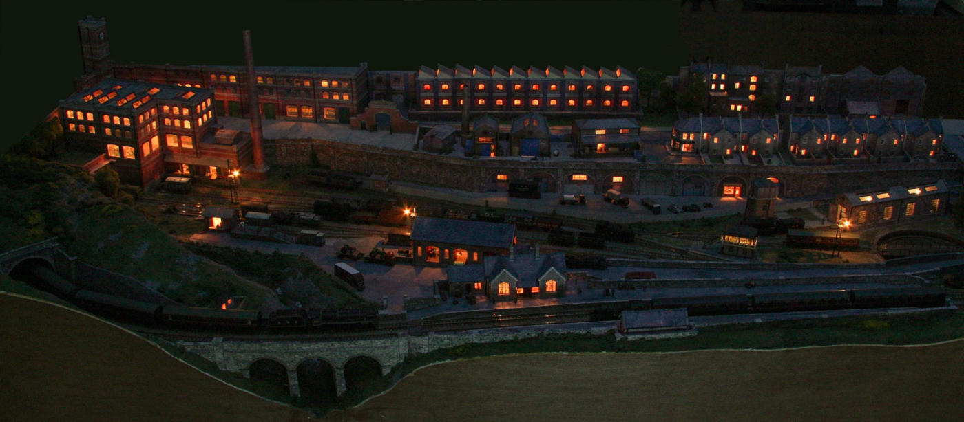
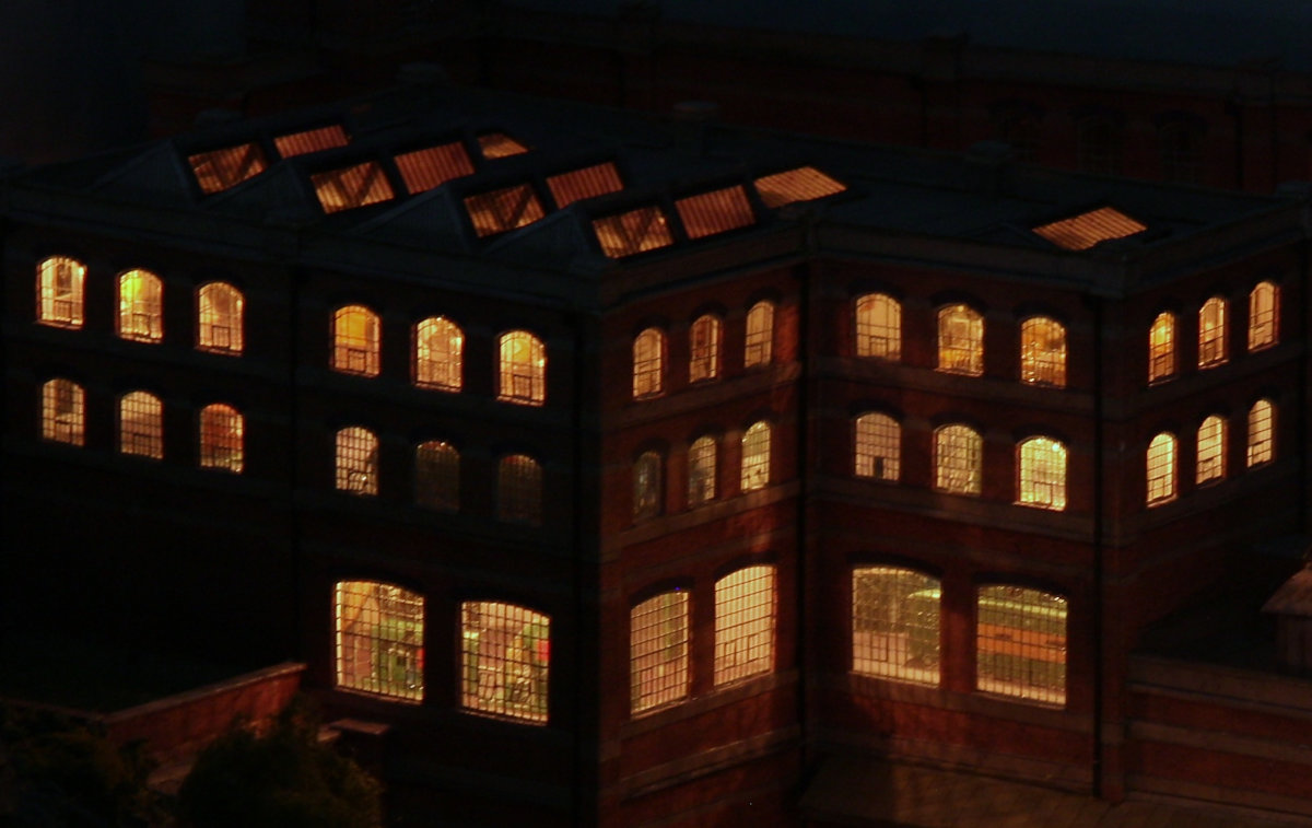
The lighting is by small filament bulbs, either the
grain of wheat or the even smaller grain of rice.
They are 12v bulbs run at 9v, for long life and
subdued glow. I find that even the warm-white
LEDs are rather harsh by comparison.
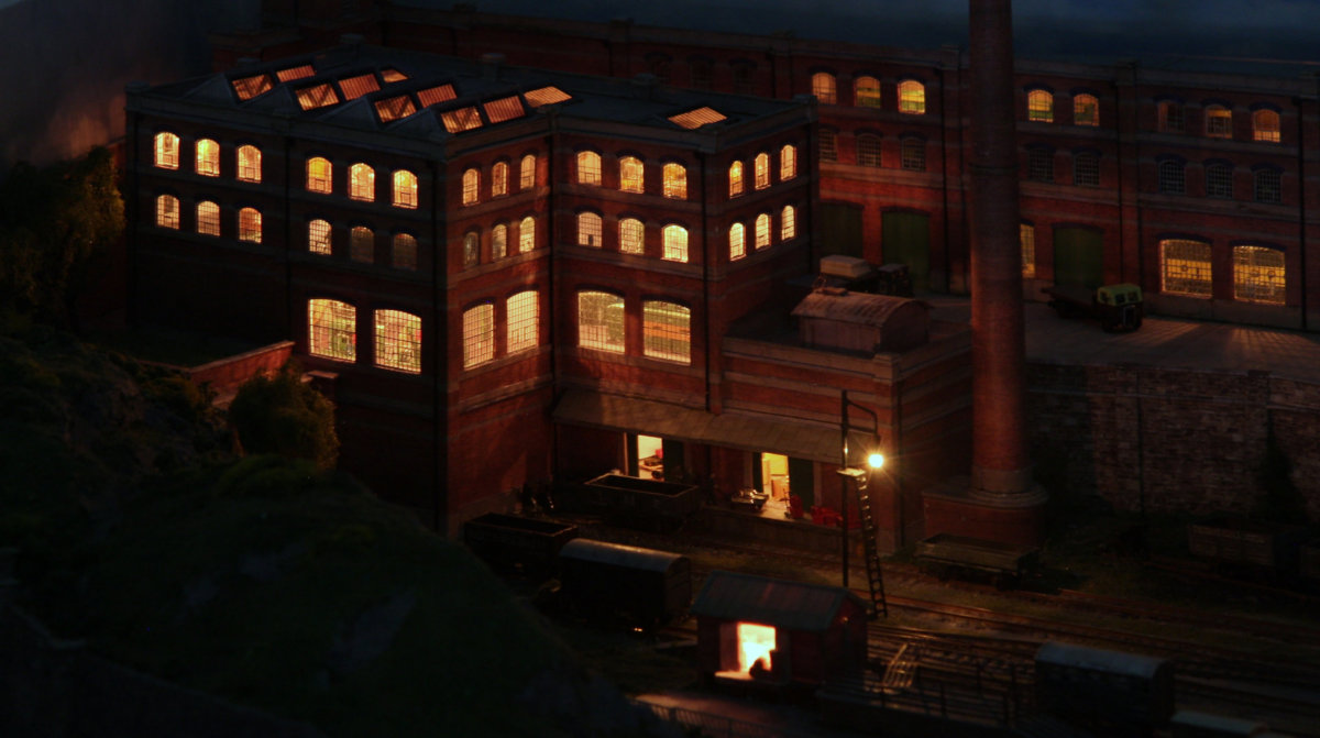
The disadvantage of using filament bulbs is their current
consumption. The grain of wheat bulbs used in the engine
and goods sheds draw 60ma each. The houses and most of
the other buildings use the grain of rice bulbs which draw
27ma. The total for Rowandale is about 3A, so it needs a 9v
4A power supply. An advantage with bulbs is you do not
have to worry about polarity of the feed.
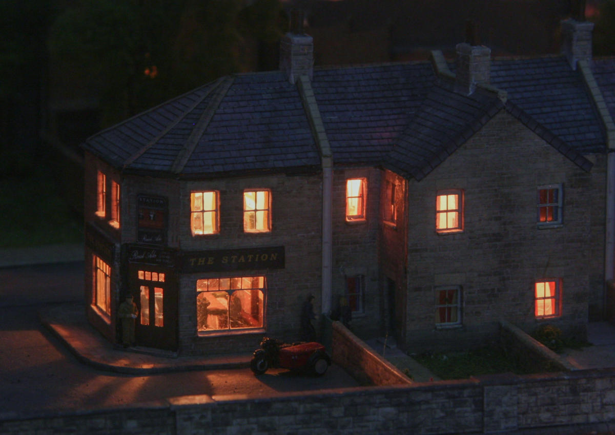
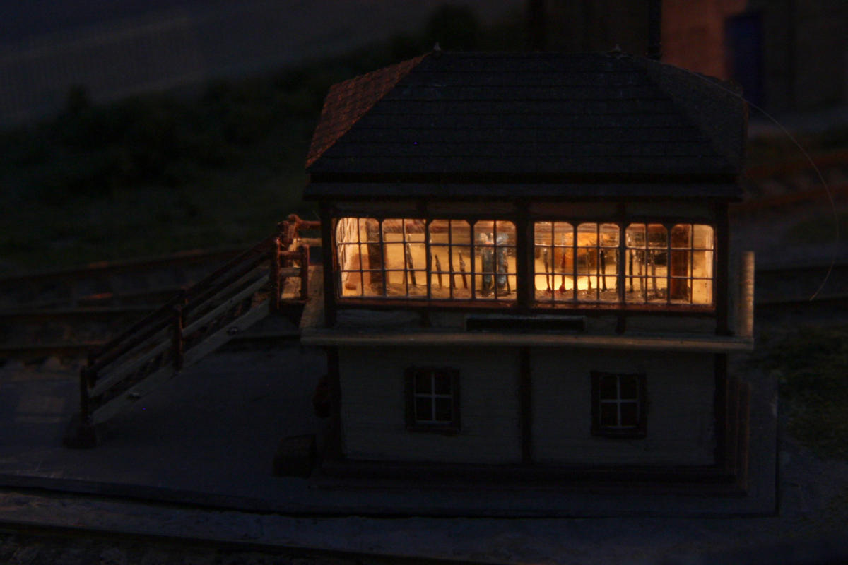
All the buildings and structures (apart from the signal
box) are built in card using the downloaded kits and
texture sheets from the Scalescenes range; some of the
building kits being heavily modified.


Once the goods yard and station section is completed then it is planned to remove the temporay ‘D’ loops
and extend the layout to a long country scene. See here for the planned extension.

This track plan shows the planned extension for the
full layout. The first section and the first corner section
are each five foot long. The next corner section is just
under 4 foot in length, with the final return loop
section being nearly 3ft by 2ft 4in. The total length of
the outer loop is 37ft; which is equivalent to one mile.
The first corner section will contain an extension of the
town, together with a section of canal, with lock and
canal basin. Then with a run over hill & dale, with
bridges and curved viaducts over a river at the other
corner. Finally will be a return loop hidden under a hill,
with a quarry and it’s siding in the front of it. Hidden
sections of track are shown faint in the track plan.
The highest point on the track will be about 2” above
the lowest track level, which is in the town sidings,
with maximum of 3% slope.

The original idea for the full layout was to extend along one wall of the room
as shown opposite, but this has now been revised to a more compact shape.


Click the buttons below to see the other sections of the layout.
The history of the development of this Station & Town Section is here: