Rowandale Moorland - Development History of Section Three


As with the previous sections, the base is made from two 50mm slabs of builders insulation board, but
this time glued together with Everbuild StixAll builder’s adhesive, which has the advantage of not having
the strong smell of Evostik Impact Adhesive. Although this glue has a high-grab it does need the two
sheets to be held together with weights for a few hours till it starts to set.
The beams with the alignment dowels and clamping magnets are set into the top edge of the upper
insulation board, adjacent to the neighbouring section, and glued in place with the StixAll adhesive.
The beams of adjacent sections are glued into their respective neighbouring sections at the same time;
ensuring an accurate match. The plywood side panels have been glued to the foam base and reinforced
with wooden corner mouldings.
The track ends have been aligned with the tracks on adjacent boards, but point motors are not fitted yet.
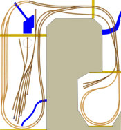
This is the track plan for the second
corner section, just under four foot in
length, which brings the double main line
on a viaduct over a wide river. The single
line from the goods yard on the first
section continues to rise up the slope to
join the main line. A single slip and point
allow to access to both the up and down
main lines. There is also a single point to
the quarry sidings, which are on the last
section.

So that trains can be run again as soon as possible, these sections will
initially just have the track bases and track laid. Points control and isolation
sections will then be connected to the computer for route selection from the
control panel. Topography, buildings and scenery will then be added to each
section in turn.


The full plan is shown here:
The development of the sections of Rowandale; are each recorded on separate pages.

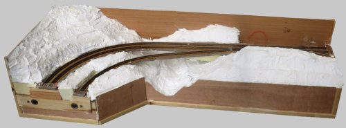
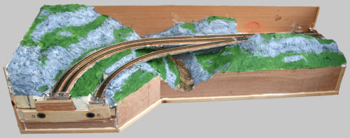

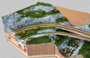
The basic shape of the topography
was built up from pieces of the
insulation foam board; these were
glued together with NoMoreNails
adhesive.
The gap at rear right, is where the
points controller will be fitted,
covered by a removable hill and
with a signal box.
This was then overlaid with
Everbuild OneStrike, low
density filler. Once this had
partly set it was smoothed
and textured with a wet paint
brush, to represent rock
surfaces and grass areas.
Emulsion paint was then used to
indicate the grass areas; later to
be covered in scenic scatter, trees
and bushes.
Deluxe Materials Solid Water will
be used to create the river, and a
viaduct will be built to carry the
tracks over the valley.
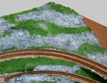
The rock faces have also been painted with
emulsion; in several shades of grey, and when
dry, washed with a darker grey to run into the
crevices. White was then used to dry-brush
highlights onto the protuberances.
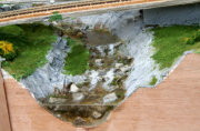
A detail is shown here.
Update
Menu
Note that the track is not ballasted yet.

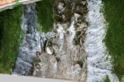
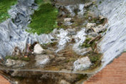
Some intermediate waterfall “dams” and small bits of broken stone were added to the river bed. The river
bed was then sealed with varnish and the front face sealed off with some stiff board, covered in plastic
tape, and the inside edge carefully sealed with a thin bead of Deluxe Materials Glue-n-Glaze, a water
soluble glue.
The river was then poured with Deluxe Materials Solid Water, a two part resin which sets crystal clear in
about a day. A second pour on the upper reaches of the river had to be poured, as the upper waterfall
"dam" had a leak to a lower level; Solid Water is surprisingly fluid till it starts to set.
Once fully set the front wall was removed, the water based glue washed off, and the raised meniscus along
the top of the front edge, trimmed off with a scalpel. Generous dabs of ModPodge-Gloss were then added to
form ripples and the waterfalls were build up with several coats.
Turbulent areas of water were formed by using partly set ModPodge applied with a stiff brush, and when
fully set, dry-brushed with white paint to highlight the rough water.
Various Woodland Scenics fine turf scatter materials were then added to the previously painted moorland
grass areas, together with bushes & flowering gorse.

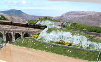
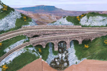
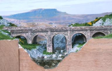
The viaducts have been built based on ScaleScenes card kits, and the track ballasted. The double track
viaduct is the main line, with the single track viaduct splitting off to join ( via Section Two ) the main
sidings in the town on the Section One of the layout.
The back scene is from a panorama of Pen-y-Ghent in the Yorkshire Dales, taken several years ago.
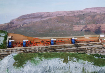
A removable section of hill, at rear right, hides the servo motors for operating the points and relays for the
sections of track that will need to be isolated when the points are set for access to the main sidings and to
the quarry sidings on Section Four. The micro-switches for the electro-frogs and isolation relays have yet to
be fitted and wired up.
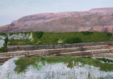
The flat area on the left of the removable section is the construction site for the planned signal box.


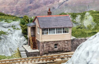
In the close up views, at right, you can see that the plastic glazing is
showing some fogging; due to me fixing an internal light into the roof with
‘super-glue’ and not leaving it overnight to fully dry off before fixing the
upper half of the box to the base. ( In the “model world” I will let you
decide whether this is due to the signalman leaving his kettle to boil too
long, or if he has sneaked in a lady friend. )
This completes the scenic work on this section, with just the electrical switching of the rail isolation
sections for the cross-over to sort out.
Photographs of this completed section are here:
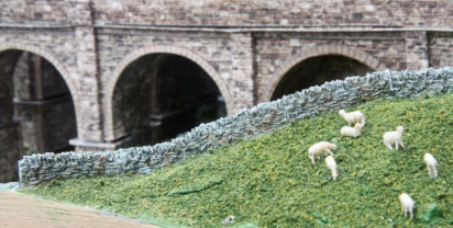
The drystone walling is produced by 3D printing in short sections by Peedie Models in Orkney. It can easily
be moulded to follow the topography, sideways or up & down, by warming in hot water for a few minutes.
The sections were glued together and to the hill using ‘gel-super-glue’, with any gaps filled with Milliput,
then painted a mid grey, followed by a dark wash to fill in the hollows in the stones. High lights were then
added by dry brushing with white and then green and brown patches for lichen etc.
The Signal Box has been added to the left hand end of the removable
sub-section; again a Scalescenes card kit, though slightly modified.


The relay logic for automatically switching the isolation sections was far more complicated than I originally
thought! This was mainly because, in addition to the normal frog switching and necessary isolation around
the cross-over, I wanted to include additional isolated sections of track; so that a loco could not be driven
close to an opposing set of points. Also it was necessary to switch polarity on the approach track to the
Sidings on Section One for certain train movements, and switching of the Quarry Sidings.
In all eight isolated/switched sections were required for the cross-over and main sidings access, and a
further three for the access to the Quarry Sidings. So in addition to the micro-switches on each of the four
servomotors which operated the points, a total of five double-pole, double-throw relays were required.
These were operated by the micro-swiches on the servos and interconnections between the relays, so as to
achive the required track switching. The relays and connections were mounted on Veroboard and fitted
between the servos {This took a little while!} hidden under the embankment to the right of the signalbox.


